
DIY Smart Alarm Clock
diy_smart_alarm_clock.md
For some time, I have been using a separate alarm clock from my phone because I need a loud alarm to wake me; however, the inconvenience of having two devices has been annoying. Several times, I have forgotten to turn it off on the weekends, and when DST came around, well, that was a whole other issue. While I could be better at remembering to enable it only when I need it and not complain about setting it, I decided to build something. I aimed to build a smart clock that retained the aesthetics of the classic 7-segment display alarm clock while integrating its functionality with that of any smartphone.
My goals were as featured: a GPS to set the time and timezone automatically; a DIY 4 digit 7-segment display that would show the time and seconds as a blinking colon between the hours and minutes; a small display that can be used to fine tune the alarms; a speaker to wake you up; a snooze/alarm off button on the front; an SD card to store any audio files to use as the alarm sound; and a headphone jack so you can connect a surround system for the speaker (because hell yea).
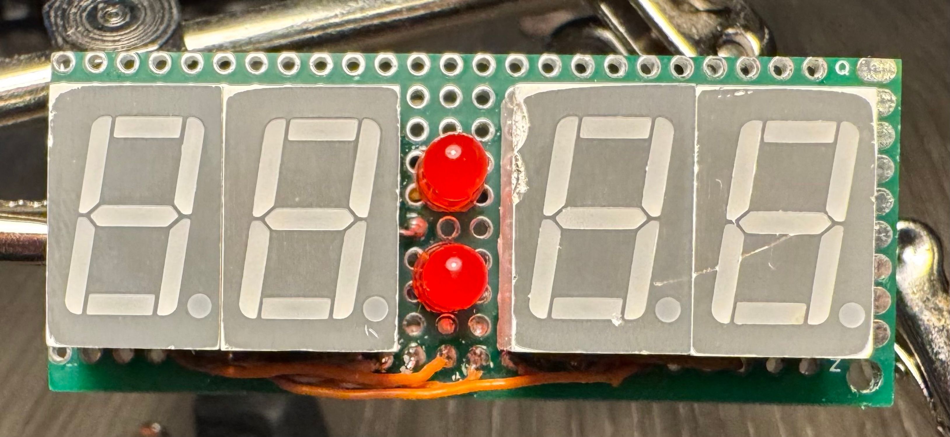
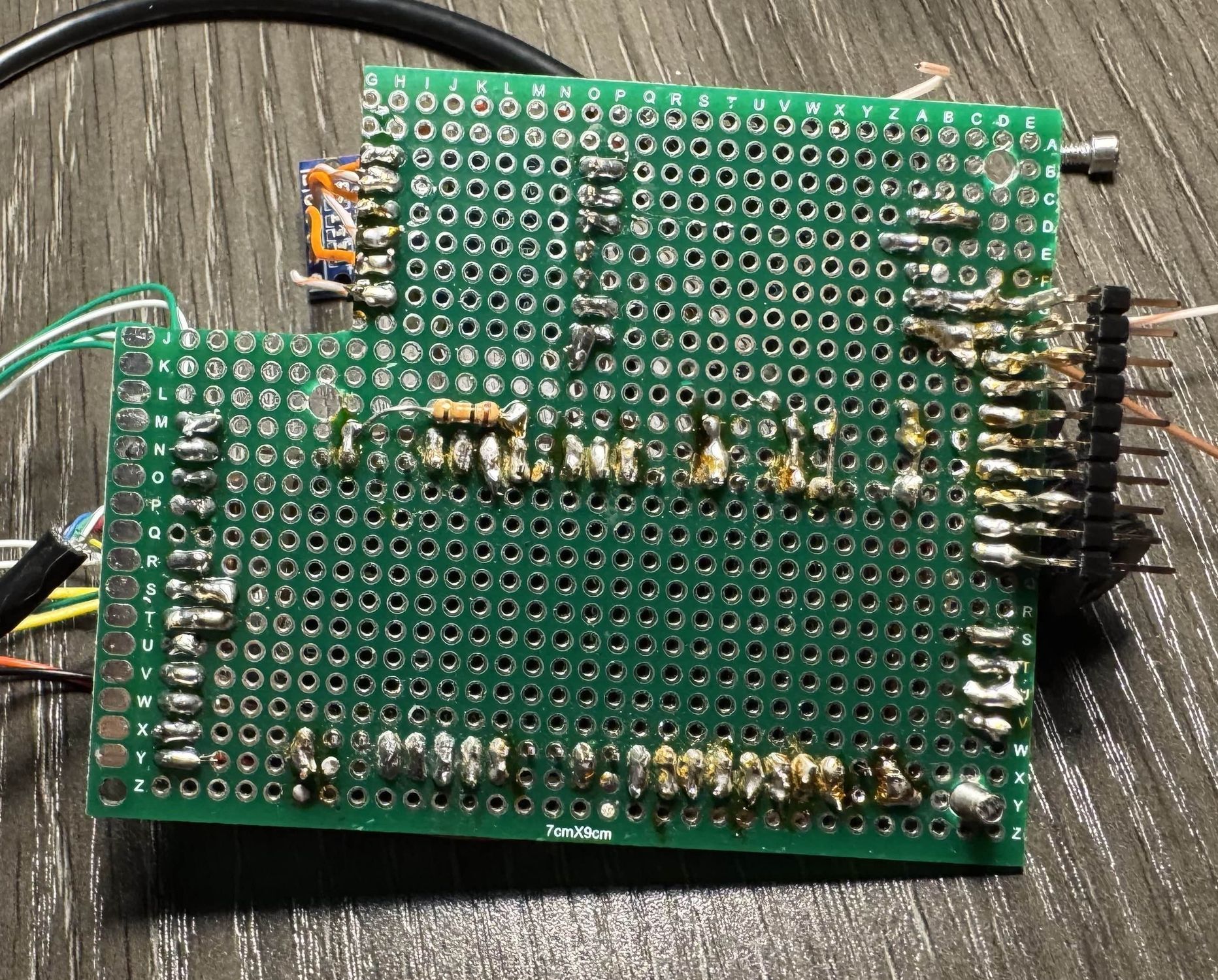
The first thing I tackled was the display, so I cut up some perfboard, basically just a blank PCB with a grid of through holes to solder things into, and put my segments on. In order to optimize space and I/O needed, I used an 8-bit shift register to allow me to put the inputs for the displays one at a time and set them to display. Instead of using a chip to multiplex, however, I just connected the enable pins for each of the displays to the microcontroller and did it in software (maybe not the most efficient option because whenever too many things are happening, the displays start to flicker, but it was the most space efficient option). To save even more space, I placed the shift register on the opposite side of the perfboard from the displays, as well as pin headers to make it modular.
Back of Display Module Front of Display Module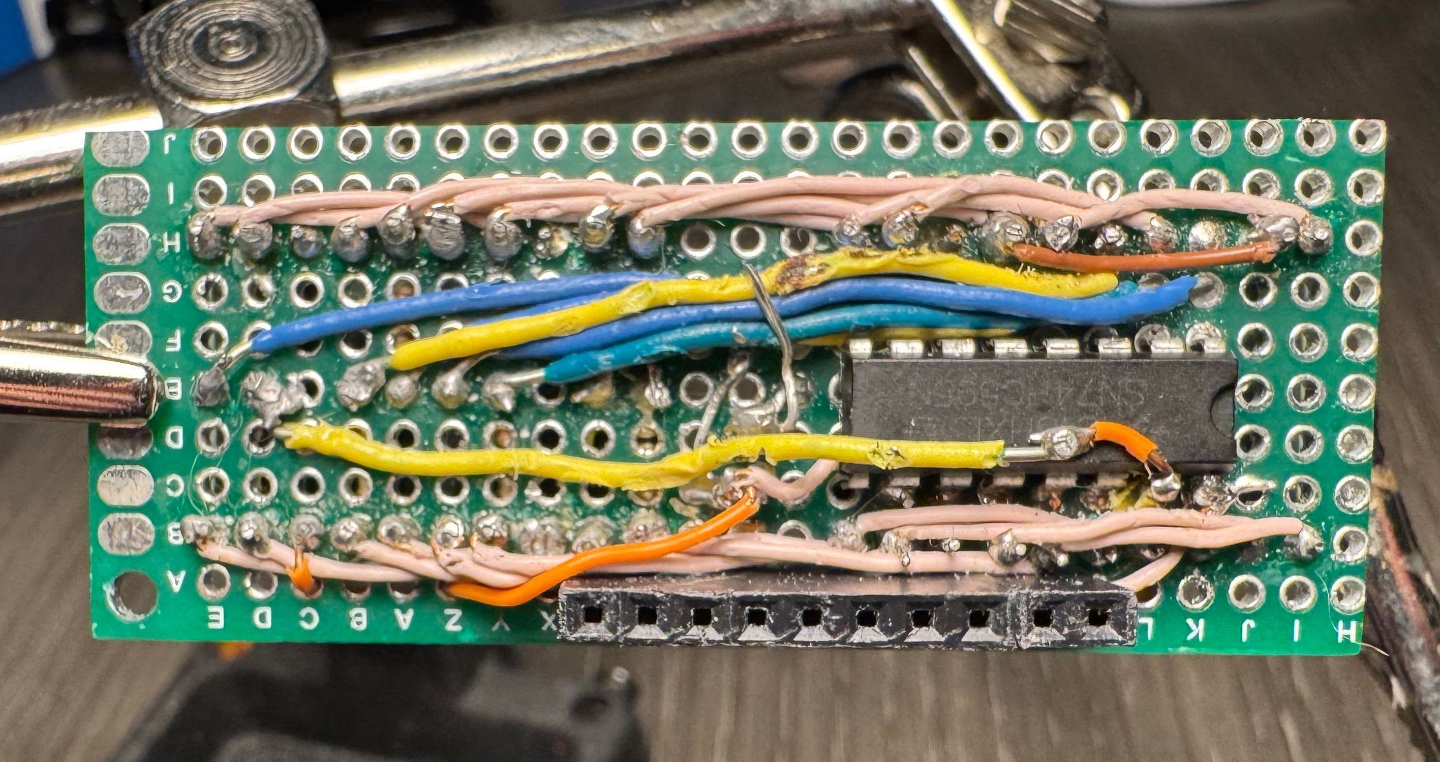
With that, a GPS and a display connected to an ESP32-S3 microcontroller, I needed to find software to run the clock. My teacher told me about a project called openHASP, which stands for Open Home Assistant Switch Plate. The original intention of the project is simply to serve as a digital switchboard for devices connected to a smart home system, but it also includes a dedicated space for custom code. I added nearly a thousand lines of code to handle all clock functionality: reading the GPS and setting the internal clock; outputting to and multiplexing the 4 7-segment displays; and functions to interface with the alarm settings, as there was no built-in interprocess communication protocol. While openHASP is technically intended to be a peripheral of the Home Assistant smart home system, communicating via the MQTT protocol, I modified it to the point that it now runs standalone, with Home Assistant serving as a peripheral to change the alarms if desired.
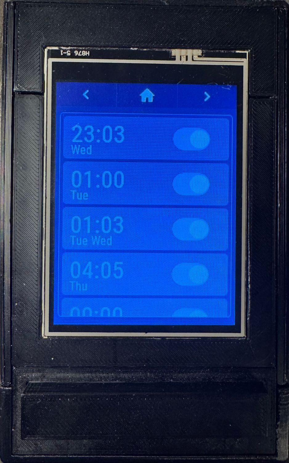
Then, using the built-in JSON description format for the displays, I designed the alarm-setting panel layout. Since I wanted so many dynamic features, like alarms appearing in a list as you create them, I had to add functions that would add display elements on the fly, and I had to make use of the ID system to keep child elements organized for even more parametric design.
Page 1 Alarm Set Page 2 Alarm Management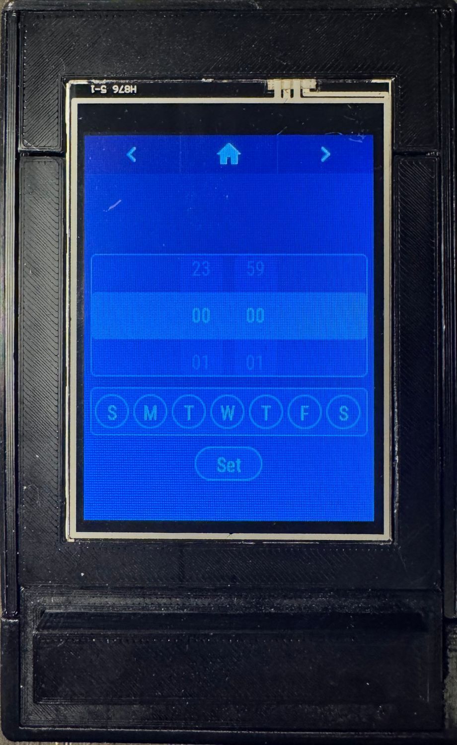
Next I worked on adding an SD card and interfacing with it so I can store a timezone database on it for the microcontroller to calculate the timezone (if im going to use a GPS to set the time, I might as well go all the way and make it set the timezone with it, despite the likelihood that I actually go anywhere with it being near zero; it's just fun to have). To calculate the timezone using the database file, I found a random program that's meant to run on the Arduino. The issue with this is that a lot of the functions that it uses don't work on the Arduino, so I had to truly understand the code and then rewrite it for the ESP32-S3, which took way longer than it should have (maybe if I actually worked before midnight, my brain would have worked faster, but we can't have that). Interestingly, it takes a good minute for the microcontroller to actually calculate the time zone because it's so computationally heavy.
When designing the overall circuitry, I used KiCad because I originally planned on making a dedicated PCB with SMD components and all that fun stuff, but when I made a test PCB that would be the size I needed to fit everything, all PCB manufacturers quoted me at $90+ and I’m not about to spend over $100 on the PCB and components on a fancy alarm clock. Since I already had perfboards from previous projects and all the individual components from the prototype, I test-fitted in Fusion360 and soldered it together.
Now that all the features and circuits were designed, I had to make a case for them, and for that, I had two goals: modular design for repairability and modifiability without reprinting most components; and a palm-sized form factor, and, if feasible, one that fits in my pocket. In the end, I designed something that used a frame with panels that slid into place and a clock face that used clips to fit.
Exploded view of the clock assembly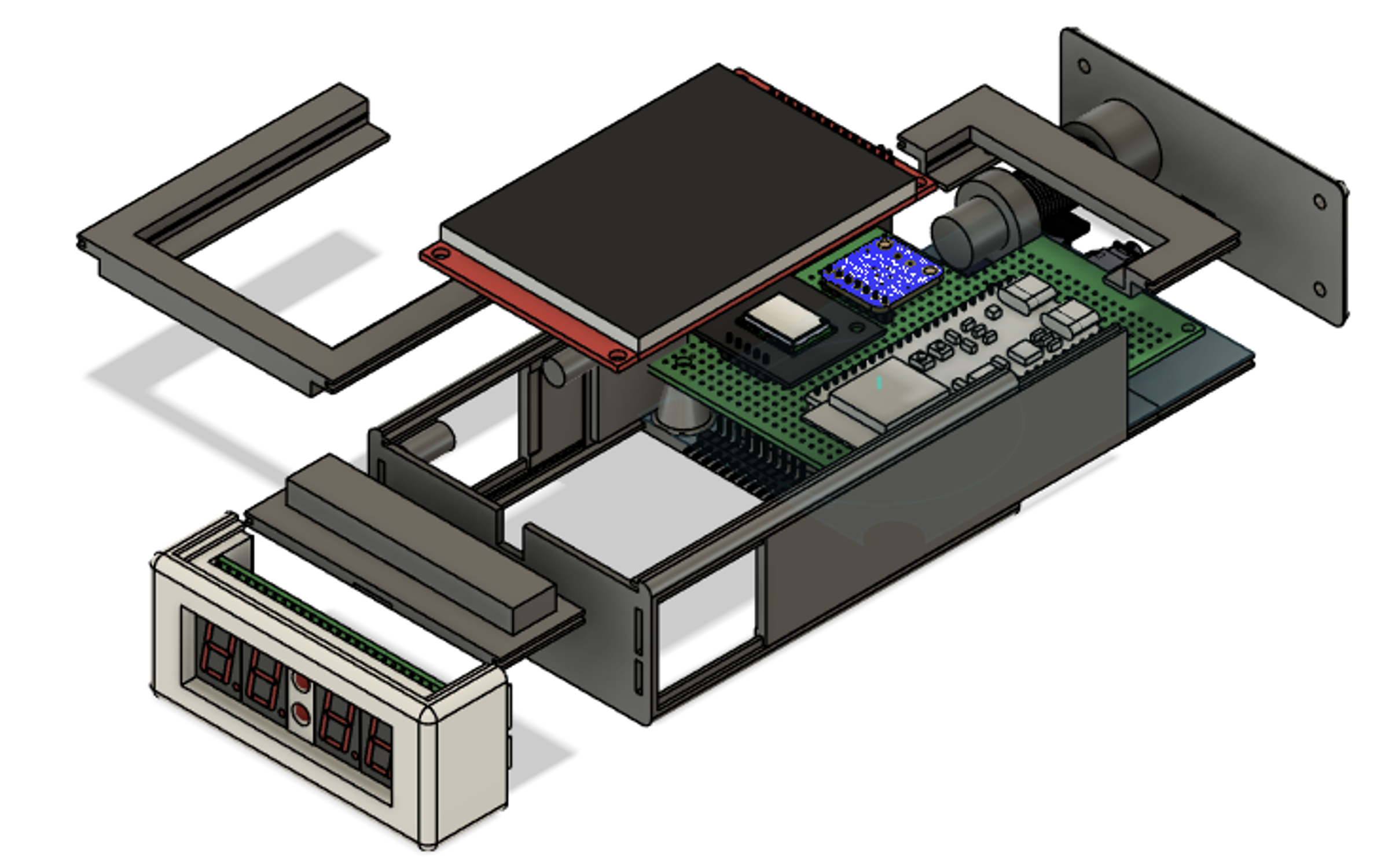
The snooze button was a fun challenge because I wanted to make it like a classic large clicky button, but since I was truly shoving everything into as small a space as I could fit, the snooze button was right on top of the display's perfboard. That left me with only as much space as the case thickness. At first, I tried to make a button that sat on top, had two guiding pillars, and was screwed on the bottom. This had the significant issue that the guiding pillars would bind up with the button pillars unless they were moved perfectly vertically, which was never going to happen in practice. My second design, I just made it the classic through button, but I made it with clearance so small that it would never even be considered in a real product (thankfully, this is just for me).
Cross section of the snooze module with measurement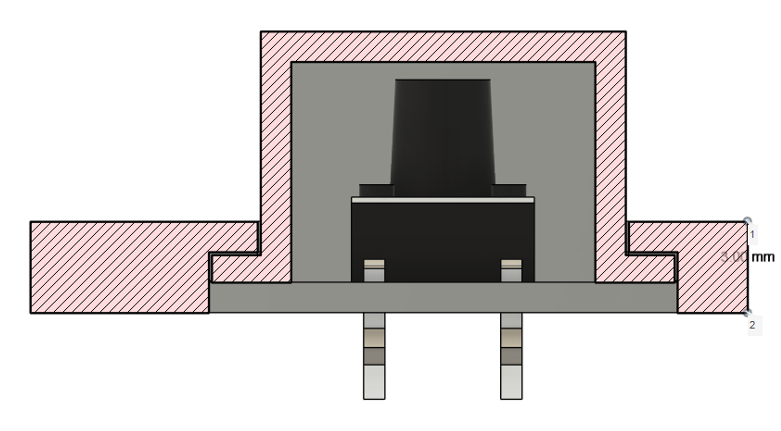
The GPS came with a small passive 1 cm^2 patch antenna, which was relatively weak, so I upgraded it to a 2 cm^2 active patch antenna that was much stronger and allowed me to set the GPS well inside my room. But since there was already next to no space, I had to hollow out a section in the already thin side wall to fit it. I already had most of the parts printed, but since I designed it with modular parts, I only had to reprint a small part if it (omg prior design actually benefited me for once).
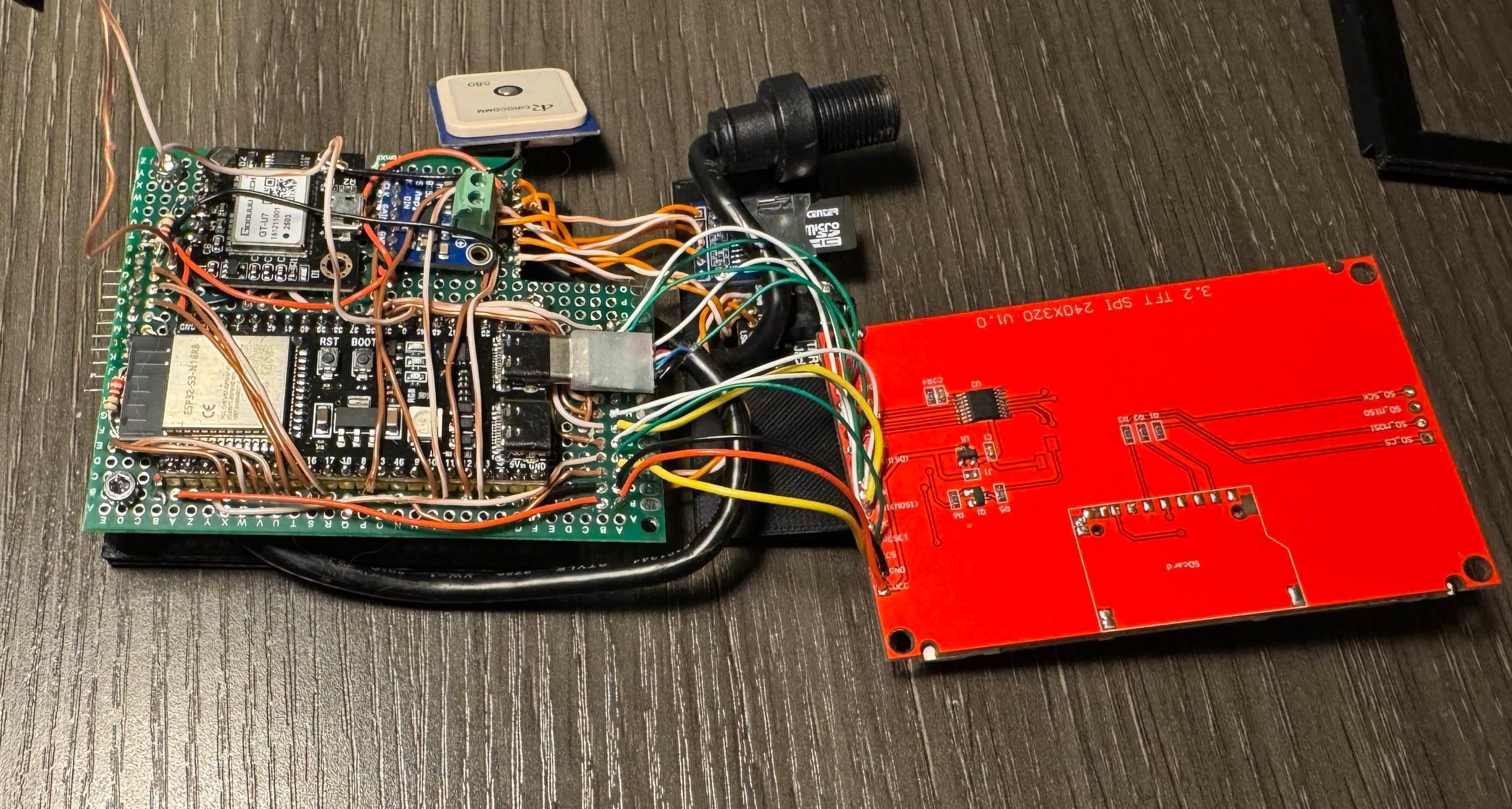
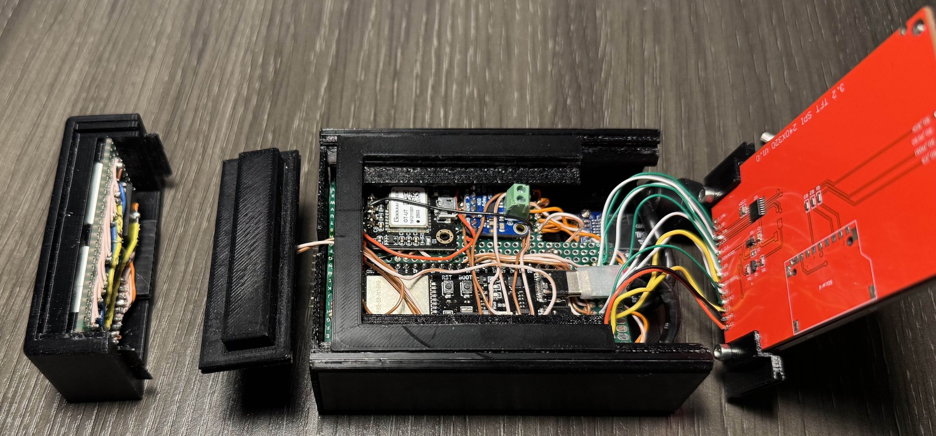
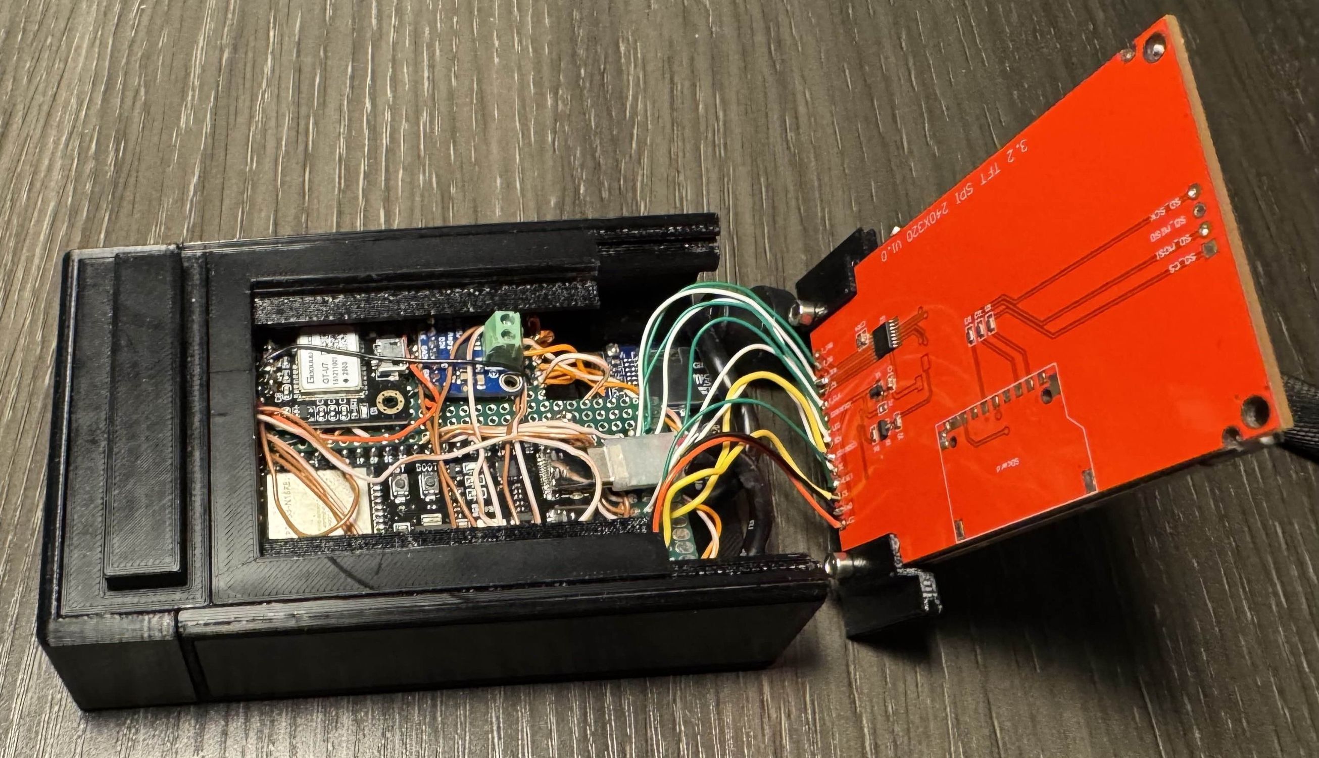
Now it was time to fully assemble it:
Laid out on the Perfboard All soldered up Everything connected and screwed onto base Base in frame with snooze Everything but the display on Fully assembled and working!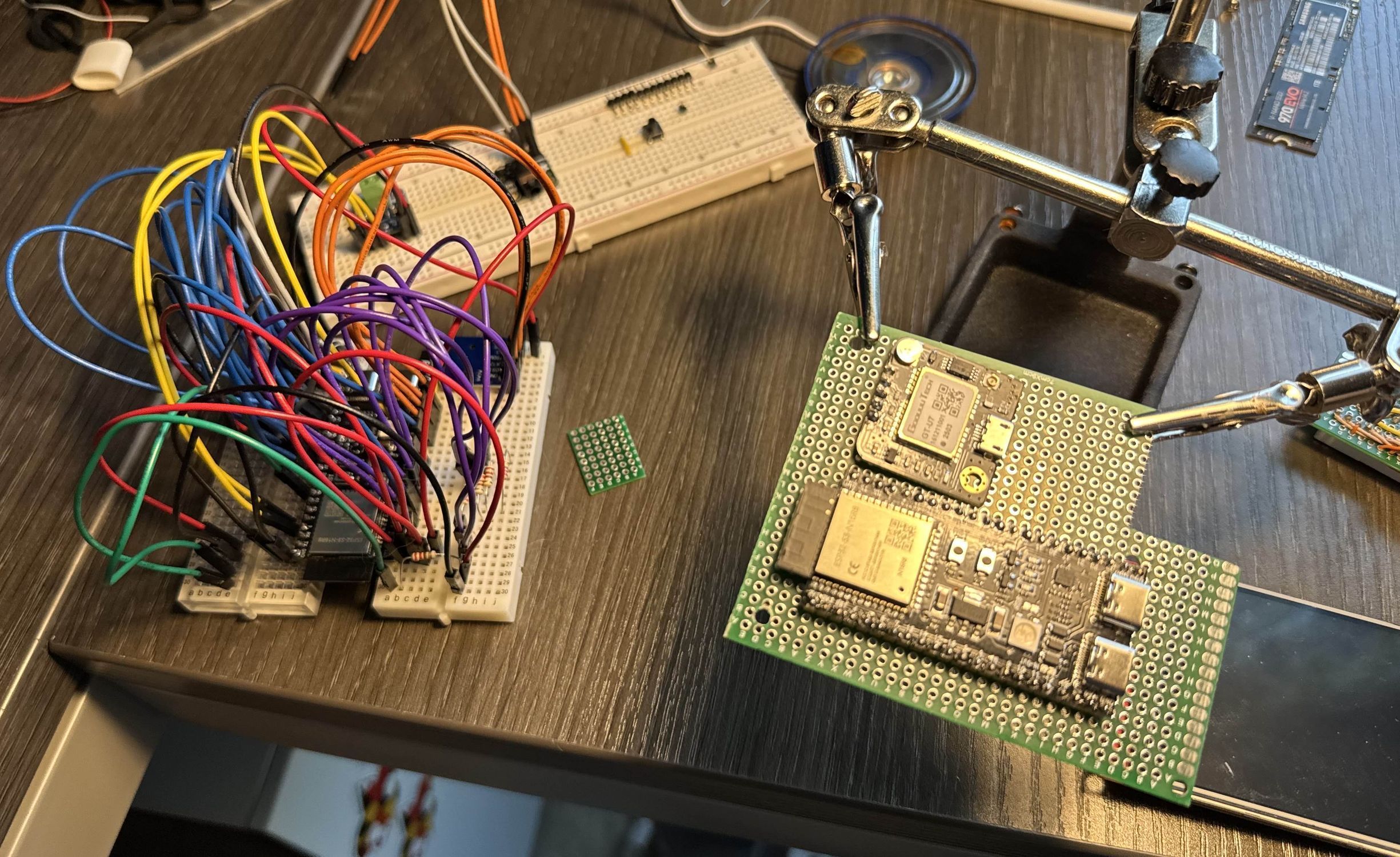
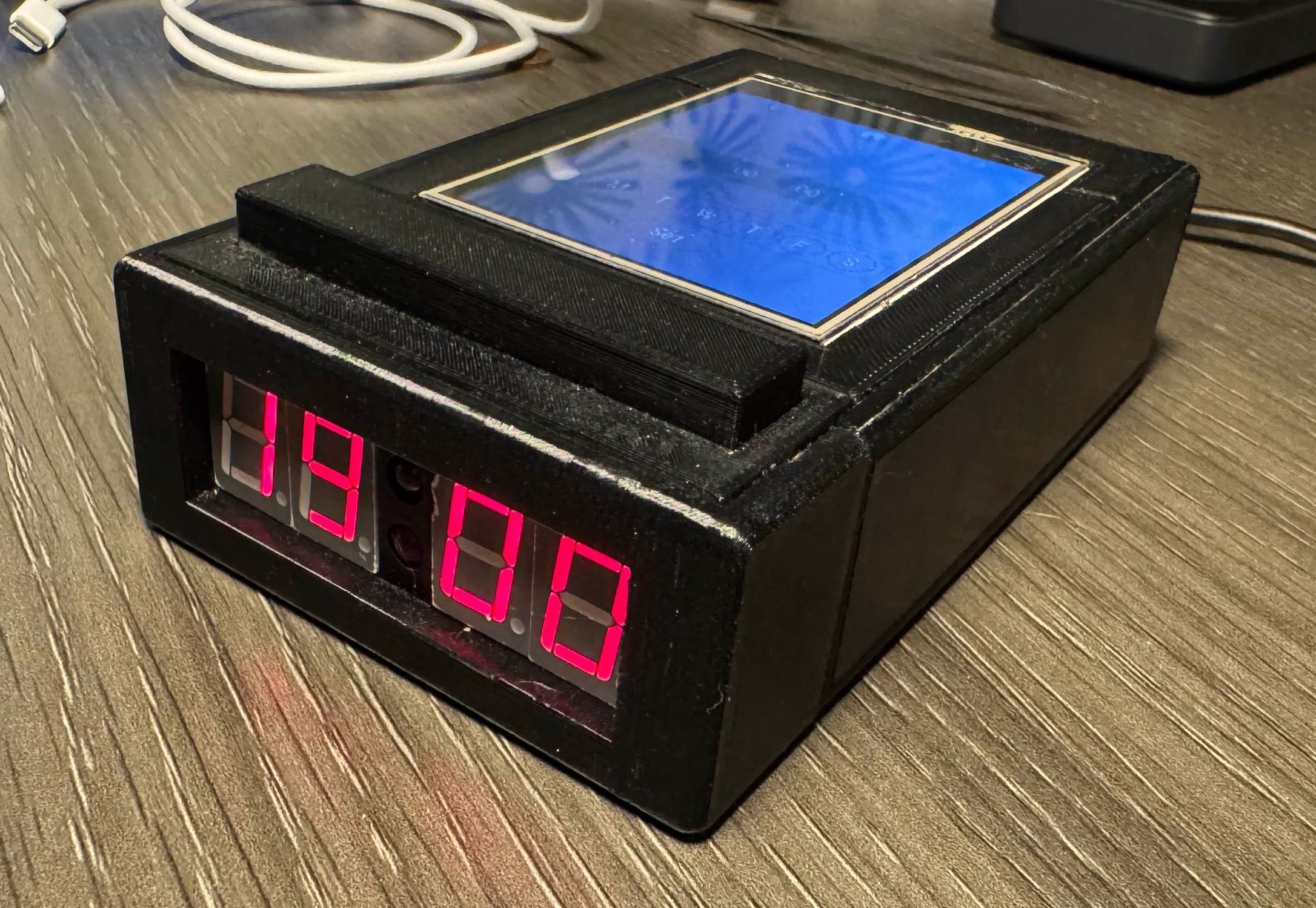
Once it was together, it was surprisingly heavy and actually was palm sized! It did kinda fit in my pockets, but not well (goal achieved though!!!). It's not quite done yet, I don't think it will ever be, but every time I look at it, I want more. I have a large speaker from an old computer sound system that would double the size, but more than double the sound volume. I also want to add a general power output so that you can connect anything as an alarm, such as an LED that powers on or strobes when the alarm triggers. There's always more to do, but for now, I will admire my own overkill alarm clock. I mean, it uses a GPS to set the time, come on, that's pretty cool.